 |
| Don't worry, it's only 3.5% alcohol - perfect for soldering! |
The NES/Famicom is available in a number of variants, and none of them can output RGB video. In the best case, it outputs composite video, and in the worst case, RF video. This has been bothering me for a while, since all of my other consoles output nice, clean RGB video to be enjoyed on my old CRT TV.
Luckily for me I live in Sweden, so RGB video has been widely available here via the EuroSCART connector since at least the 80's. I never knew this was a European thing until I started learning about different video signals some years ago, and my childhood hate for the SCART connector has since been turned to deep appreciation :)
One quite recent way of getting the NES to output RGB video is to order the NESRGB kit form the brilliant gentleman Tim Worthington in Australia, who created this incredible piece of hardware.
The kit can be ordered here for AU$99 + shipping, which for me amounted to a total of 800 SEK ≈ 94 US dollars for comparison.
http://etim.net.au/shop/shop.php
That's roughly what I paid for my top loading NES2 a few years ago. As it turns out, it's well worth the money! As an added bonus, it's also a really nice project to work with, and it provided excellent exercise in soldering/modding.
There are installation guides as Tim's website, but none of them specifically covers the top loading NES so I thought I'd write something about it. I'd like to point out though that I am not a professional in any way, nor have I any kind of education when it comes to soldering etc. I have been practicing a lot for some years though, and so far all of my modification projects have been successful.
There may be errors in my described methods, but I think this guide might be helpful for somewhat proficient amateurs similar to myself. If someone discover any grave error, please drop a comment.
Also, this is not a complete guide for each step of the process so you might wonder why I even write it in the first place. Well, when I did the mod I only wanted to document my work, not write an installation guide. This guide isn't better than Tim Worthington's guide, but there might be some differences that are good to know about. Maybe it's more a documentation on what I did, not what you should do.. :)
The images are available in a higher resolution, should you need it. Just open the image in a new tab or something, and you should be able to view the original image.
The first thing you need to do is to unscrew the four screws in the bottom to open the unit, and then unscrew the RF shielding and the two screws by the cartridge connector, to get access to the circuit board. I haven't got any pictures of this, but that should be self-explanatory.

This is what my unit looks like, and I've marked the PPU. This is the chip that needs to be removed by desoldering first of all.

I don't have a soldering iron with a built-in solder pump, so I removed the solder from these pins by heating up the solder with my iron, and then sucked away the liquid solder with a simple solder pump. It took about one hour and it was by far the most tedious task for this project. However, it shows that it's not too difficult to do, using cheap equipment.
You could probably use desoldering braid, but I found that to be far less efficient than just using the pump.

On this picture, the desoldering is close to done. Some pins were very easy to get free, and some were very difficult. When you've removed as much solder as possible from each pin, gently push the pin sideways with a flat-head screwdriver until you hear that the small amount of solder still holding the pin in place, breaks. If the pin starts to bend, or you need to apply too much force - keep suckin' or braidin' around the pin and try again. I felt I wanted to be very careful here not to break the pins.
This little neat tool is great for lifting chips without hurting them.


I started to lift the chip, only to notice that one leg in the corner was stuck. I tried and tried to remove all the solder but it felt close to impossible. Finally the leg broke in half, but that's OK. Fixing a broken leg or to actually turned out to be easy. I had done a composite video mod for this unit before, and for that I needed to cut the pin connected to +5V so that pin needed to be repaired anyway.
I guess I was lucky, because this leg also broke, very close to the top of the chip, leaving only a tiny spot to connect the new leg. So in total, I had to repair two pins. I put some solder on the broken connection to the chip and then attached a small piece of hard, straight wire. That turned out really well, and the chip got a pair of nice new legs.

Clean the holes from excess solder, making them nice and clean. Is should look something like this.

Insert the socket in place, make sure to align it correctly to make things easier (and consistent). Just look at the hole on the right side. Then insert the round pin strips into the socket. The kit includes two round pin strips and two square ones.

Place the adapter board on the socket and solder all of the pins in place. You can now remove the board from the socket. Then turn everything upside down and solder the socket in place. The next steps, on how to solder the square strips and the second socket to the NESRGB board, were not documented. These steps are carefully explained in Tim's guide here
http://etim.net.au/nesrgb/installation-famicomav/
These steps are identical for the AV Famicom and the top loading NES.

This is what my NESRGB board looked like with everything soldered in place, and the PPU placed in the socket. The broken, repaired pins are on the other side, but they fit well and made good contact.
Since the top loader outputs NTSC video, bridge jumper J5 with some solder, and then bridge jumper J3 for power. I have no interest in other palettes than the original (neutral) palette, so I bridged pin 3 to GND (see the picture above).
The top loader, as opposed to the AV Famicom, normally does not have the multi AV out port. There are many ways of solving this with different connectors and cables, but I really wanted to use original Nintendo AV port. I had a broken SNES laying around, so I desoldered the port and mutilated the back of my NES a little, to fit it as you shall see later. There are certainly better ways of doing this to make it look nice, but this is one way I guess.
Anyways, you want to wire everything up correctly for this to work with an official cable.

Looking at the port from above, with the pins pointing upwards, it looks like this. I only want the original mono audio without any modifications, so I bridged pin 11 to pin 12 first of all to provide the same audio to both of the channels.
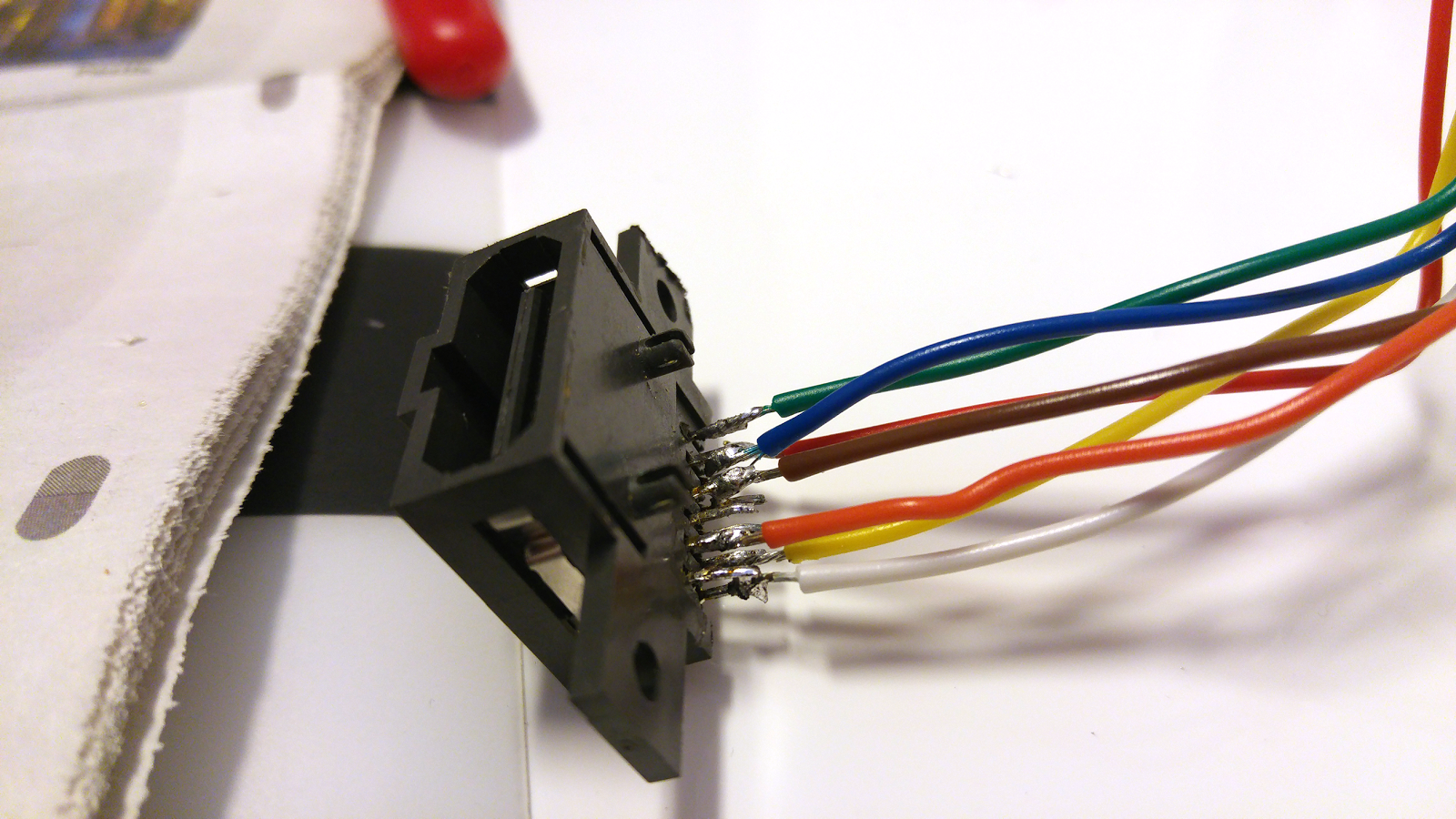
Using coloured wires is simple, and helps tremendously. I used the following colours:
Red: red
Green: green
Blue: blue
Ground: brown
Sync: yellow
+5V: orange
Audio: white
It's worth mentioning that this configuration does not use composite video as a sync signal. You can use composite video, but that often leads to nasty interference in some colours, so it's better to use the luma (Y) signal. As a consequence this port doesn't output composite video at all, as if that was a problem. However, if you for some reason would like that, just connect pin 9 to V (composite video) on the NESRGB board instead.
(This is a common problem with cheap SNES RGB cables, and I can really recommend buying a cable that uses luma for sync if you're having this problem with your SNES. I never noticed this when I was only playing on my CRT TV, but when I recently started to capture the video it became very apparent, and unacceptable. This cable can be found here:
https://www.retrogamingcables.co.uk/games-consoles/nintendo/super-nintendo/super-nintendo-pal-rgb-av-scart-cable-lead-cord-for-sale
This cable is not compatible with the NESRGB though, it's only for the SNES)

It's always a good idea to protect the solder joints with some shrink tube. Solder the other end of each wire to the matching place on the NESRGB board. The audio pin is found on the bottom of the NES circuit board though:

The audio pin is marked above.

Here, everything is soldered in place. As you can see, the yellow cable that is used for sync is connected to luma (Y). I also fixed the AV port with some tape.

This is the result. I know it looks like ass, but it's very functional. The final thing to consider is very important, and that is to use the proper cable for this to work. There are quite a few different cables floating around with this connector, and you can't just use any of them.
I ended up modifying an NTSC SNES cable by removing the three capacitors that are normally found on pins 7, 11 and 15. This is the pinout for my cable:

It's not easy to make a fair comparison by photos on a CRT TV, but here's what I've got:


The difference is colossal. The image is so clean, and the colours are so nice and vibrant, but these pictures aren't enough to show the difference.

This is what Power Blade looked like when I captured the composite video signal using Elgato Game Capture HD.

RGB. Wow, just ... wow. It's even more apparent in motion, check these videos:
Power Blade, composite video
Power Blade, RGB video
Please watch in 720p60. The quality really blows my mind! Tim Worthington is a genius. Thank you so much for this incredible piece of hardware.
Inga kommentarer:
Skicka en kommentar